
raytracing(orthographic projection)
Categories: Computer Graphics
Before we start
- DirectX11 use left handed coordinates.
- Aspect ratio: width / height
Line intersecting Circle🧿
Our purpose is to draw a sphere in the virtual space.
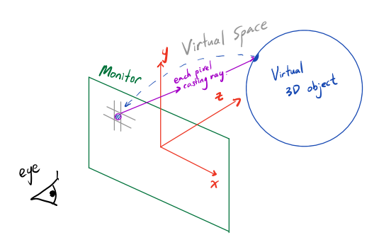
Assume that the 3D object which is shown in the monitor through our eyes is inside the virtual space. This space is similar to reality and each color component and more are expressed by the object’s property and various interactions from different light sources. The coordinate system is defined so that z axis is in the direction of entering the monitor.
Now assume that each pixel within the monitor cast a ray in the direction of (0, 0, 1). Some rays might intersect this 3d object, some might not, while most of them intersect the object twice(considering the object is the circle as shown in the diagram)
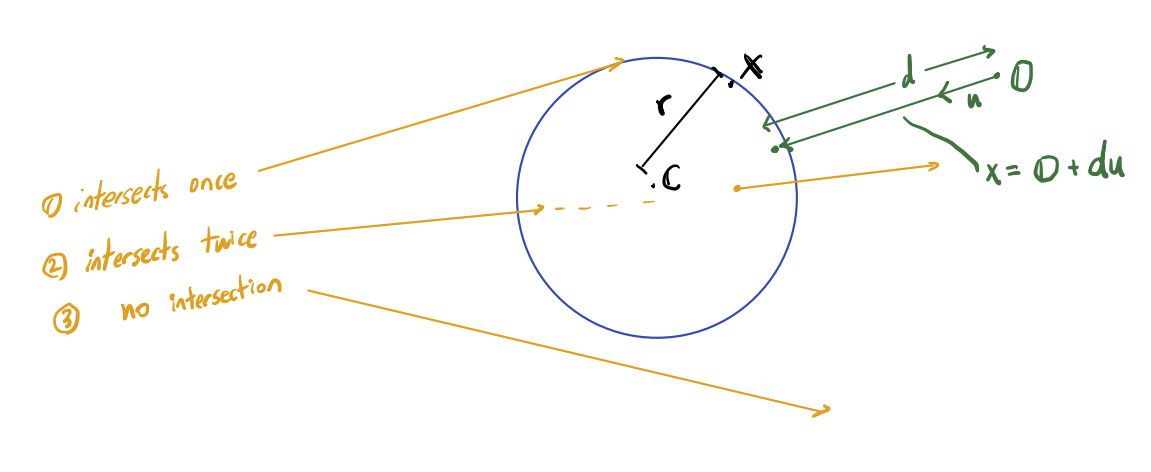
We could mathematically formulate the ray’s intersection from the sphere and a line equation. The results are as follows
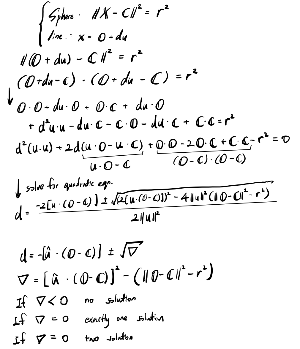
now we have formula for drawing circles into a screen.
Code😎
Note that this code requires extra components to actually function.
class Ray
{
public:
    glm::vec3 start; // start position of the ray
    glm::vec3 dir;   // direction of the ray
};

class Hit
{
public:
    float d;// ray's direction from start to collision
    glm::vec3 point;// point of collision
    glm::vec3 normal;// surface normal of the collision
};


void raytracing(std::vector<glm::vec4> &pixels)
{
    ////make the screen black
    std::fill(pixels.begin(), pixels.end(), vec4{0.0f, 0.0f, 0.0f, 1.0f});

    for (int j = 0; j < height; j++)
    {
        for (int i = 0; i < width; i++)
        {
            //Move from Screen coordinate(data saved from the top left coordinate hence (0,0) located at top left corner)
            //to World coordinate(has origin at the center)
            const vec3 pixelPosWorld = TransformScreenToWorld(vec2(i, j));

            //All the ray facing same direction -> Orthographic projection.
            const auto rayDir = vec3(0.0f, 0.0f, 1.0f);

            Ray pixelRay{pixelPosWorld, rayDir};

            pixels[size_t(i + width * j)] = vec4(traceRay(pixelRay), 1.0f);
        }
    }
}


glm::vec3 TransformScreenToWorld(glm::vec2 posScreen)
{
    const float xScale = 2.0f / (this->width - 1);
    const float yScale = 2.0f / (this->height - 1);
    const float aspect = float(this->width) / this->height;
    return glm::vec3((posScreen.x * xScale - 1.0f) * aspect, -posScreen.y * yScale + 1.0f, 0.0f);
}

vec3 traceRay(Ray &ray)
{
    const Hit hit = sphere->IntersectRayCollision(ray);

    if (hit.d < 0.0f)
    {
        return vec3(0.0f);
    }
    else
    {
        return sphere->color * hit.d; //temporary ways to sense the space
    }
}

Hit IntersectRayCollision(Ray &ray)
{
    Hit hit = Hit{-1.0f, vec3(0.0f), vec3(0.0f)}; // no collision if d == 0

    //frome our equation
    const float b = 2.0f * glm::dot(ray.dir, ray.start - this->center);
    const float c = glm::dot(ray.start - this->center, ray.start - this->center) - this->radius * this->radius;
    const float nabla = b * b / 4.0f - c;

    //if there is collision.
    if (nabla >= 0.0f)
    {
        const float d1 = -b / 2.0 + sqrt(nabla);
        const float d2 = -b / 2.0 - sqrt(nabla);
        hit.d = glm::min(d1, d2);

        hit.point = ray.start + ray.dir * hit.d;
        hit.normal = glm::normalize(hit.point - this->center);
    }

    return hit;
}
Result
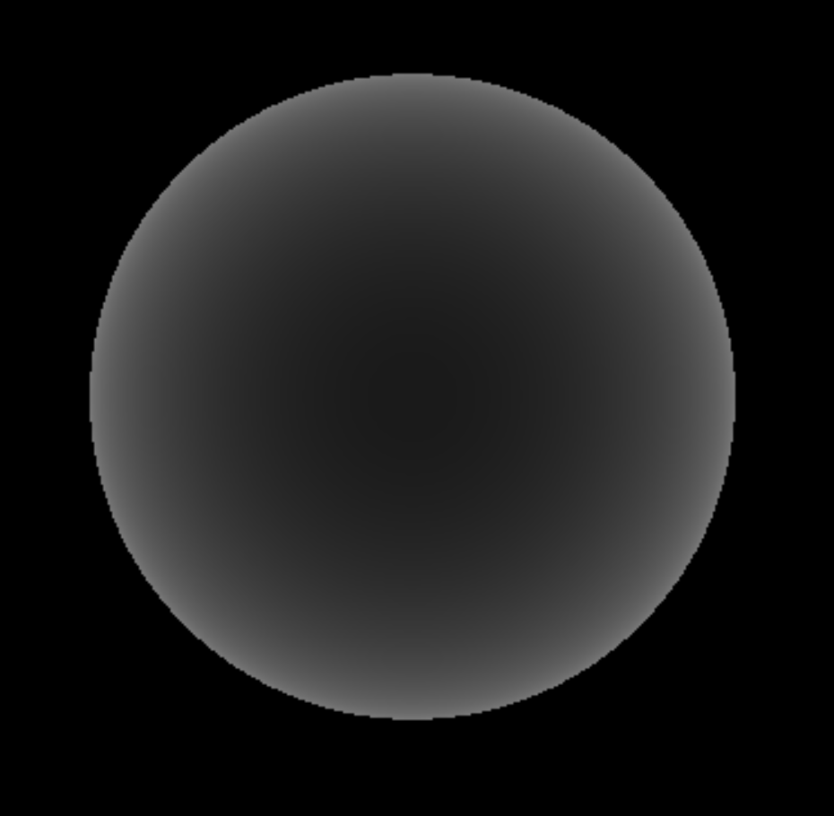
We were able to draw 3D object using ray tracing under orthographic projection(even though its not perfectly depicting the attributes of the 3d sphere in real time). We would investigate in the later post to make this more realistic by adding lighting and more.
Leave a comment